T/S series electronic expansion valves are designed for use in air conditioning and refrigeration systems or in heat pumps. The valve controls the automatic adjustment of refrigerant flow rate and makes the system work under optimized conditions for the purpose of fast cooling or heating, precise temperature control and energy saving. The valve can also be used e.g. for suction line pressure controls. These valves provide bidirectional operation to control the refrigerant flow rate in heating or cooling mode.

- APPLICABLE FOR OIL-FREE SYSTEM (T SERIES)
- SMALLER INSTALLATION SPACE: LOW HEIGHT, SMALL VOLUME, LIGHT WEIGHT
- OPTIMIZED FLOW PATH DESIGN FOR NOISE REDUCTION
- FAST OPERATION, ENERGY SAVING
- APPLICABLE FOR REVERSIBLE SYSTEMS LIKE HEAT PUMPS: BIDIRECTIONAL FLOW
- Applicable for all common HCFC and HFC refrigerants such as: R22, R134a, R404A, R407C, R410A, R507A …
- Cooling capacity: 3,5 to 105 kW (R22 nominal capacity)
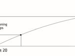
- 500 steps (full stroke); 32 ± 20 opening steps
- Medium temperature TS min./max.: -30°C /+70°C (duty cycle rate below 50%)
- Ambient temperature min./max.: -30°C / +60°C (duty cycle rate below 50%)
- Relative humidity: : 0 to 95% RH• Installation position: :
– Coil installed in the upwards position, valve rotor central axis within ±15° versus vertical axis – Inlet connection preferably sidewise, outlet preferably downwards
Rated voltage: 12V DC(± 10%), rectangular wave
• Actuating mode: 4-phase 8-step permanent magnet
stepping motor of direct-acting type
• Excitation mode: 1 ~ 2 phase excitation, monopole actuation
• Excitation rate:
– Seat Ø 1,3 to 3,2 mm: 30 to 90pps
– Seat Ø 4,0 to 6,5 mm: 30 to 40pps
• Activation of self-holding mechanism: Maintain excitation in
stop position min. 0,1~1,0 sec.
• Min. motion time from completely open to completely closed:
– Seat Ø 1,3 to 3,2 mm: 6s @ 90pps
– Seat Ø 4,0 to 6,5 mm: 13s @ 40pps
• Coil current:
– Seat Ø 1,3 to 3,2 mm: 260mA/phase (20°C)
– Seat Ø 4,0 to 6,5 mm: 375mA/phase (20°C)
• Coil resistance:
– Seat Ø 1,3 to 3,2 mm: 46 ± 3.7 Ω/phase (20°C)
– Seat Ø 4,0 to 6,5 mm: 32 ± 3.2 Ω/phase (20°C)
• Insulation class of coil: E
• Protection class: IP 67
| Valve Model | Part Number 1) | Seat ɸ
(mm) |
Kv (m3/h) | Nominal Cooling Capacity 2) [kW] | MOP Max.
Oper. Press. [MPa] |
MOPD
Direct [MPa] |
MOPD
Rev. (MPa) |
||||
| R22 | R134a | R407C3) | R404A
R507A |
R410A | |||||||
| DPF(T01)1.3C-07 | DPF-09001 | 1,3 | 0,05 | 4,7 | 3,6 | 4,8 | 3,3 | 5,5 | 4,5 | 3,5 | ≥2.1 |
| DPF(T01)1.65C-05 | DPF-09002 | 1,65 | 0,08 | 7,8 | 6,0 | 8,0 | 5,5 | 9,1 | |||
| DPF(T01)1.8C-08 | DPF-09003 | 1,8 | 0,1 | 9,4 | 7,2 | 9,7 | 6,6 | 11 | |||
| DPF(T01)2.0C-03 | DPF-09004 | 2 | 0,16 | 11,5 | 8,9 | 11,8 | 8,1 | 13,5 | |||
| DPF(T01)2.2C-01 | DPF-09005 | 2,2 | 0,2 | 15 | 11,6 | 15,5 | 10,5 | 17,6 | |||
| DPF(T01)2.4C-01 | DPF-09006 | 2,4 | 0,23 | 20,7 | 15,9 | 21,3 | 14,5 | 24,2 | |||
| DPF(TS1)3.0C-01 | DPF-09007 | 3 | 0,39 | 30,8 | 23,7 | 31,7 | 21,6 | 36 | ≥1.5 | ||
| DPF(TS1)3.2C-01 | DPF-09008 | 3,2 | 0,43 | 36,3 | 28 | 37,4 | 25,4 | 42,5 | |||
| DPF(S03)4.0C-01 | DPF-09010 | 4 | 0,5 | 42 | 32,3 | 42 | 29,4 | 50,4 | ≥0.7 | ||
| DPF(S03)4.5C-01 | DPF-09011 | 4,5 | 0,7 | 53 | 40,4 | 52,5 | 36,8 | 63 | |||
| DPF(S03)5.5C-01 | DPF-09012 | 5,5 | 0,9 | 70 | 53,9 | 70 | 49,0 | 84 | |||
| DPF(S03)6.5C-02 | DPF-09013 | 6,5 | 1,1 | 105 | 80,9 | 105 | 73,5 | 126 | 3,0 | ||
Note:
1) Extent of delivery without coil
2) Nominal working conditions: Condensing Temperature 38°C; Evaporating Temperature 5°C; Sub-cooling 0K; Superheat 0K
3) Nominal capacity is got at 480 fully open pulses of linear flow curve
This information is based on values calculated using the NIST REFPROP Database (NIST Standard Reference Database 23, Version 9.0, Lemmon, E. W., Huber, M. L.,and McLinden, M. O., Thermophysical Properties Division, 2010).
Critical temperature: 71°C
Saturation points (bubble and dew points at same composition).
| Temperature (°C) | Pressure (bar) | Liquid
Phase Density (kg/m3) |
Vapor
Phase Density (kg/m3) |
Liquid
Phase Enthalpy (kJ/kg) |
Vapor
Phase Enthalpy (kJ/kg) |
Liquid
Phase Entropy (kJ/(kg.K)) |
Vapor
Phase Entropy (kJ/(kg.K)) |
||||||||
| -40 | 1,8 | 1313 | 7 | 142 | 405 | 0,77 | 1,90 | ||||||||
| -35 | 2,2 | 1297 | 9 | 149 | 407 | 0,80 | 1,89 | ||||||||
| -30 | 2,7 | 1280 | 11 | 156 | 410 | 0,83 | 1,88 | ||||||||
| -25 | 3,3 | 1263 | 13 | 163 | 412 | 0,86 | 1,86 | ||||||||
| -20 | 4,0 | 1245 | 15 | 170 | 414 | 0,89 | 1,85 | ||||||||
| -15 | 4,8 | 1227 | 18 | 178 | 416 | 0,92 | 1,84 | ||||||||
| -10 | 5,7 | 1209 | 22 | 185 | 418 | 0,94 | 1,83 | ||||||||
| -5 | 6,8 | 1190 | 26 | 192 | 420 | 0,97 | 1,82 | ||||||||
| 0 | 8,0 | 1170 | 31 | 200 | 421 | 1,00 | 1,81 | ||||||||
| 5 | 9,4 | 1150 | 36 | 208 | 423 | 1,03 | 1,80 | ||||||||
| 10 | 10,9 | 1129 | 42 | 215 | 424 | 1,05 | 1,79 | ||||||||
| 15 | 12,6 | 1106 | 49 | 223 | 425 | 1,08 | 1,78 | ||||||||
| 20 | 14,5 | 1083 | 57 | 232 | 426 | 1,11 | 1,77 | ||||||||
| 25 | 16,6 | 1059 | 66 | 240 | 426 | 1,14 | 1,76 | ||||||||
| 30 | 18,9 | 1033 | 77 | 248 | 426 | 1,16 | 1,75 | ||||||||
| 35 | 21,4 | 1006 | 89 | 257 | 426 | 1,19 | 1,74 | ||||||||
| 40 | 24,3 | 976 | 103 | 266 | 425 | 1,22 | 1,73 | ||||||||
| 45 | 27,3 | 943 | 120 | 276 | 424 | 1,25 | 1,72 | ||||||||
| 50 | 30,7 | 907 | 141 | 286 | 422 | 1,28 | 1,70 | ||||||||
| 55 | 34,4 | 865 | 167 | 297 | 419 | 1,31 | 1,68 | ||||||||
| 60 | 38,4 | 815 | 201 | 308 | 414 | 1,35 | 1,66 | ||||||||
| 65 | 42,8 | 748 | 250 | 322 | 406 | 1,39 | 1,63 | ||||||||
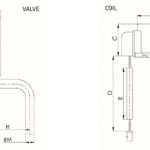
| Valve Model | Coil Series | Valve Dimensions [mm] | |||||||||||
| F | G | H | Ød | ØN | |||||||||
| DPF(T01)1.3C-07 to DPF(T01)2.4C-01 | PQ-M10 | 78 | 36 | 30 | 6,35 | 17,35 | |||||||
| DPF(TS1)3.0C-01 to DPF(TS1)3.2C-01 | 82 | 40 | 30 | 7,94 | 17,35 | ||||||||
| DPF(S03)4.0C-01 to DPF(S03)6.5C-02 | PQ-M03 | 148 | 64,7 | 63,4 | 15,88 | 35,3 | |||||||
| Valve Model | Coil Model | Coil Dimensions [mm] | Coil Product Number | ||||||||||
| ØA | B | C | D | E | |||||||||
| DPF(T01)1.3C-07 to DPF(TS1)3.2C-01 | PQ-M10 012-000277 | 38,5 | 26,4 | 25,6 | 700 | 600 | DPF-58013 | ||||||
| DPF(S03)4.0C-01 to DPF(S03)6.5C-02 | PQ-M03 012-000001 | 67,5 | 42,4 | 33 | 700 | 600 | DPF-58002 | ||||||